Robot Kinematics - Controlling your robot using mathematics!
A project activity for Girls Into Coding.
This session is designed to be fun! The idea is that we can follow it together online, but that we can be free to move at our own pace. We’re going to be doing some basic python programming in this activity. If you’re not too familiar with Python, don’t worry, you’ll be able to follow along :) !
Contents
Resources
Here's some resources that may help with the activity
What is Kinematics?
You might be wondering, what in the world is ‘kinematics’?
Well, it’s just a fancy name we give to the study of movement.
Cars move, cats move, humans move, and of course, robots move. We use kinematics to not only figure out where we will end up once we’re done moving, but also to figure out how we need to move to get somewhere. Scientists have been using kinematics for a long time to figure out how things roll, bounce, fly, walk, anything you can think of that involves moving!
But what does it have to do with robots?
When you want to make a robot move, you want to make sure it will get to where you want it to go. It’s a little bit like Google Maps, but just for your robot.
Let me give you an example:
I’m going out for a walk. I go out of my house, walk down the road, take the second left, and keep walking for two blocks.
But where am I going??!?
I’m controlling where I turn and how far I walk, but I don’t actually know where I will end up. Forward Kinematics will help me figure out where I will end up if I take these turns and where I will be from where I started.
As you can see, I end up at the park.
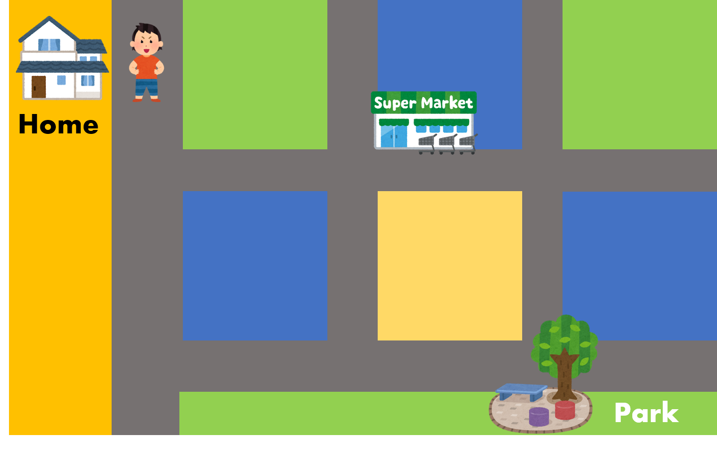 Cartoons Copyright of Irasutoya
What if I want to get to the supermarket, but I don’t know how? (You can see how this sounds a lot like Google Maps.)
I know where the supermarket is from where I am now, but I don’t know which turns to take to get there, or how far to walk. Inverse Kinematics helps me figure out what turns I need to take to get where I want to go.
Okay, let’s get to the fun bit!
Let’s build the first part of our robot arm!
Activity #1
Robot Arm Assembly - A little journey through mechanical design
First, we need to start to build our robot arm. Expand the headings below (click on them) to see each step of the instructions.
- 1 microbit
- 1 kitronik robotics board
- 2 Stepper motors
- 1 Bag labelled 'Assembly parts'
- 2 3D printed robot arm links (labelled 1 and 2)
- 1 base board (white in color in 4 pieces)
- 1 x AA 4 battery holder
- 1 whiteboard marker
- 1 screwdriver (looks like a pen)
- 2 jumper leads (4 wires each)
- 1 usb cable


Bag contains:
- 2 x 3D printed parts (bearing holder and caster holder)
- 2 x bearings (or 1 bearing if 1 is already in one of the robot arm links)
- 5 x screws (M3 x 6mm countersunk screws) [Includes 1 spare]
- 3 x nuts (M3) [Includes 1 spare]


The motor connector ports should line up with the Robotics board ports as shown in the figure. Make sure there aren't any crossovers in the wires! That means the same colour wire in port 1 on the motor connector on the left should be the same colour wire on port a on the Robotics board on the right.


Testing the first motor
Activity #2
Whenever we’re building a robot (or anything) it’s really important to test it works in stages! We’ve just put our first motor together, so now lets test that it works :)! Follow these instructions to check your motor is moving correctly!
Take the robot arm #1 and place it so that the small 'D' shape in the green part of the robot arm lines up with the motor shaft. You should be able to push the two together gently. Now give the robot arm a gentle turn to check it rotates.


First of all let's test the microbit is working. Enter the following code into the python
You can transfer this code into your python either by typing it in, or by copying and pasting. Please be careful to make sure you enter it exactly the same! Where you put spaces, tabs, brackets, full stops and other punctuation is really important in python because these characters tell the computer how to understand your code!
If you've got any problems with this you can follow this guide to resolve them: Link here
You should see your microbit display light up and the code run! Observe what happens on the microbit display.
- Can you change the text to your name?
- Can you change the image to another type? (Tip: look at this link)
If it doesn't work check your code and connections, something is wrong there. And please remember you can always ask for help!


You can download the code we will use from this link.
This link will download a python file to your computer.
Next, in your python editor click on 'Load' and then select the python file you just downloaded (it's called: main_rotation.py). The code will load and you will see it on your screen.
- If you didn't see the picture of the snake, something is wrong with the software! -> Check your code!
- If your robot arm isn't moving then there maybe something wrong with your connections! -> Check your battery is switched on and check all your wires are securely in their connections (give them a gentle tug).
- If you accidentally press the microbit symbol the code will switch to control motor #2, we don't want this at the moment, so if you do see the number 2 being displayed then just press the microbit symbol on the microbit once to reselect motor #1!
- How can you get the motor to move further when you push the A or B button?
- How do you get the microbit to display a different picture when it starts up?
If you have any problems with any of the previous tasks make sure to tell a mentor so that we can solve them together! :)
Building the second part of our robot arm!
Activity #3
Let’s build the second part of the robot arm!
Your current progress on building the arm should look something like the picture - if not have a check of the previous steps or let a mentor know.


Take two M3 screws out of the 'assembly bag'. Line the holes up between the green motor mount and the gray robot arm link. Insert each screw one at a time, then use the right sized screwdriver attachment to tighten the screw. You need to turn it clockwise to tighten it! A good way to remember this is the phrase "righty tighty, lefty loosy".


This is a clip on part. It clips onto the robot arm link #1. Look at the pictures and clip it on now.


Move the arms so that the whiteboard marker is positioned at the position X = 9 and Y = 0. This is the 'home' position for the robot arm, we will talk about what this means shortly. This is the same position as in the photo below


Testing the second part of our robot arm!
Activity #4
Whenever we’re building a robot (or anything) it’s really important to test it works in stages! We’ve just put our second motor together, so now lets test that it works :)! Follow these instructions to test the second motor and link of the robot arm!
Your current progress on building the arm should look something like the picture - if not have a check of the previous steps or let a mentor know.


- If you didn't see the picture of the snake, something is wrong with the software! -> Check your code!
- If your robot arm isn't moving then there maybe something wrong with your connections! -> Check your battery is switched on and check all your wires are securely in their connections (give them a gentle tug).
- If you accidently press the microbit symbol the code will switch to control motor #1, we don't want this at the moment, so if you do see the number 1 being displayed then just press the microbit symbol on the microbit once to reselect motor #1!
- If your microbit seems unresponsive, then just try to give the reset button a push and see if that helps!
Let’s recap kinematics!
Activity #5
Joints and Grids
I’m going to introduce some new terms!
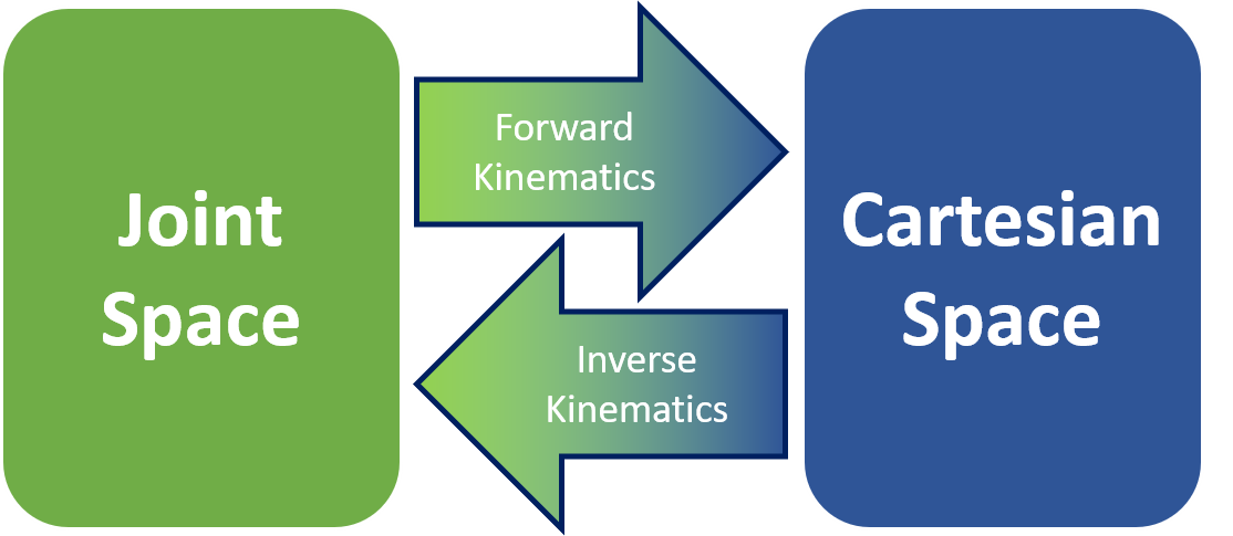
When we work with certain robots, we like to talk about the Joint Space and the Cartesian Space. They’re just two ways of describing where our robot is, or its state. I’ll show you in a bit what these terms mean, but first I’ll show you where Forward and Inverse Kinematics fits into all this. I’ll come back to this diagram later and you’ll understand it better.
Let’s try moving in the Joint Space!
When we talk about Joint Space, we are describing what each joint of the robot is doing. Joints are places where the robot can move, and usually connect two rigid bodies. We use joints and links to try and simplify the mathematics we need to do.
A good example of this is our own human arm! If I were to make a very simple drawing of how my arm moves, I’d have a shoulder joint, an elbow joint, and a wrist joint. The bones in between are links.
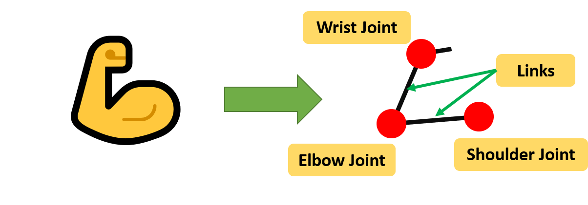
If you observe our robot arm, it uses revolute joints. These are joints that only rotate, a bit like like the hinges in your room door!
We’ve made a little animation that you can use to try and understand what it means to control the robot in joint space.
See the Pen Robot arm (Joint Angles v1) by Ben (@benisme) on CodePen.
Have a play around with it, and see if you can understand what values you can give the joint, and what it will make the joint do!
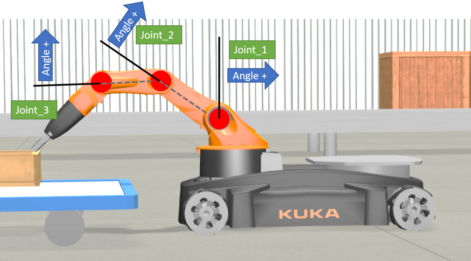
The picture below might help you understand what the values mean for a more complex robot. The black lines indicate where ‘zero’ is for that joint, and I’ve put down the direction that are positive values.
What about Cartesian Space?
Activity #6
After playing about with the Joint Space, maybe you’re getting the hang of it. Now just imagine if you had a robot with lots more joints! Like twenty. What about robots like these?
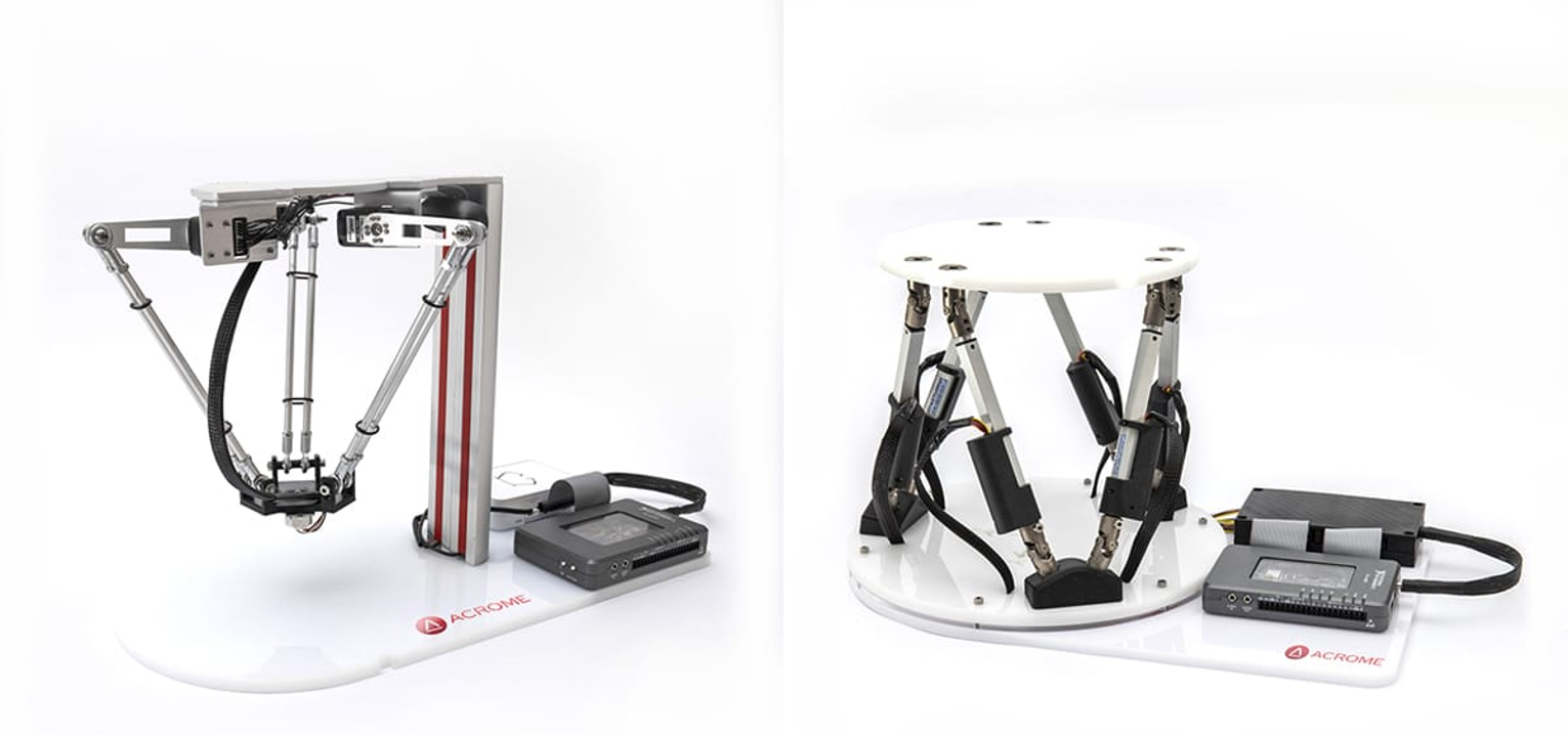 Images Copyright Acrome Robotics
That’s a lot of joints you’d have to control! It wouldn’t be easy using joint space alone.
Now I’m going to introduce you to Cartesian Space. You might have heard of things like coordinates. Coordinates are a way of talking about the position of things, and Cartesian is a system of coordinates. If you know maps, you’ll have heard of longitude and latitude, it’s a bit like that.
The Cartesian coordinate system in 2-dimensions (a flat surface!) uses 2 axes: x and y to describe where a point is on that plane. For example, in the image below the cat is at x = 2 and y = 3. Or we can write it as (2, 3) with brackets. So if I told you to put the cat at (2, -3), where would I put it?
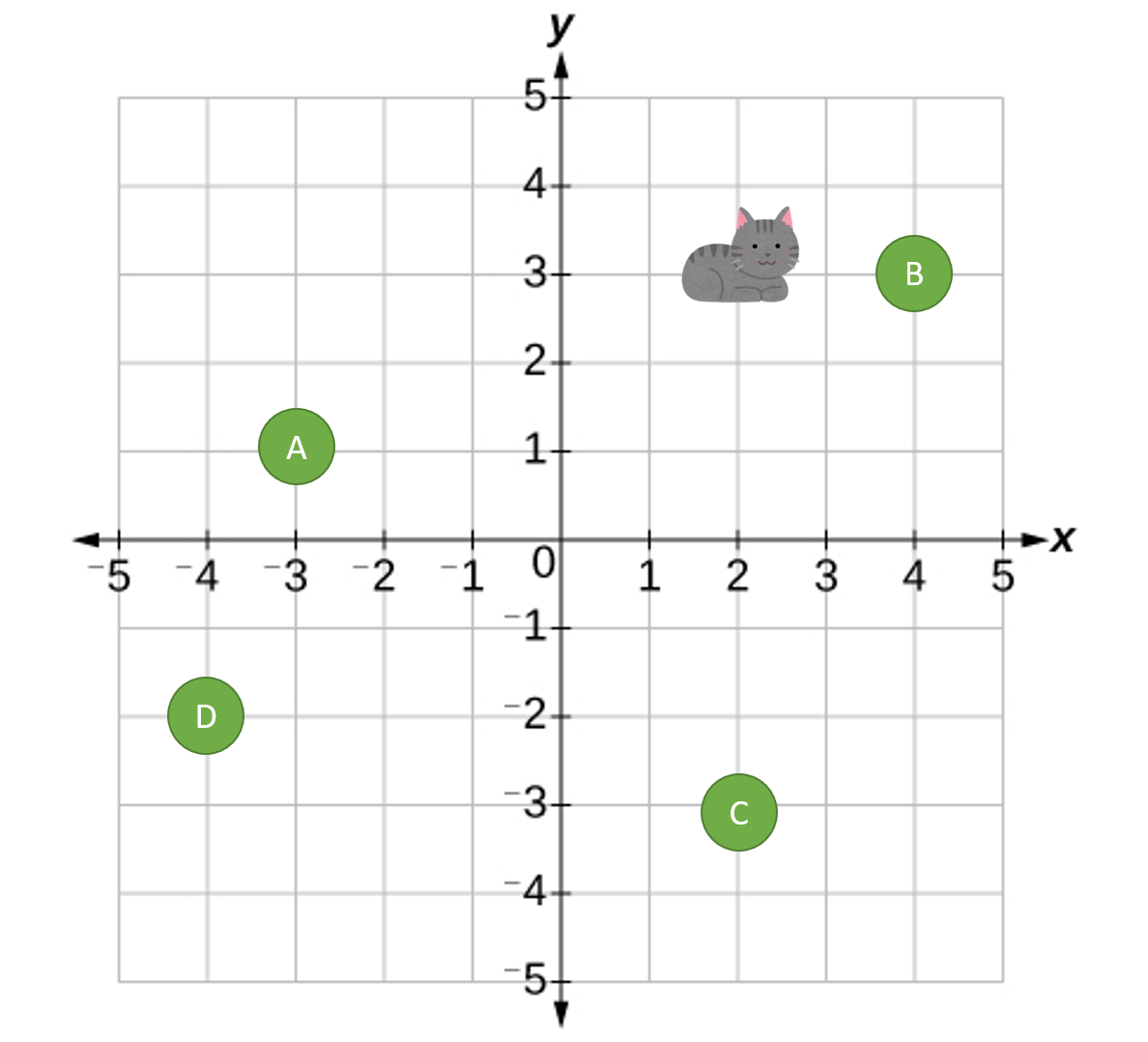 Cat Image Copyright of Irasutoya
Okay, so now you have the idea. Here is an image of the robot and a grid over it, with x and y axis measurements. Any point within the pink area (also called the workspace) is a place the end of the robot can reach.
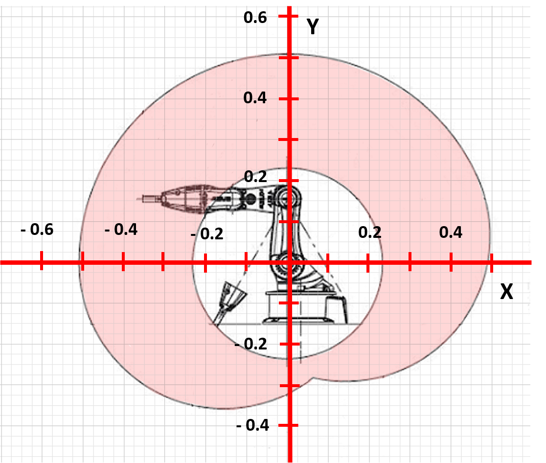
This is exactly the same as for our simple robot arm!
Let’s move in Cartesian Space!
Activity #7
In this activity, we’re going to try and make the pen touch a flower!
The arm should look something like the picture - if not have a check of the previous steps or let a mentor know.

You can download the code we will use from this link.
It will download a python file to your computer. In your python editor click on 'Load' and then select the python file you just downloaded (it's called: main_cartesian.py). The code will load and you will see it on your screen.


Next touch the microbit logo button, the robot arm should move to the approximate position x = 5, y = 5.
- If you didn't see the picture of the ghost, something is wrong with the software! -> Check your code!
- If your robot arm isn't moving then there maybe something wrong with your connections! -> Check your battery is switched on and check all your wires are securely in their connections (give them a gentle tug).
- If you accidently press the a or b button, the code will move the arm to a different position, we don't want this at the moment. So if you do do that just press the resest button on the microbit and try again! :)
- If your microbit seems unresponsive, then just try to give the reset button a push and see if that helps!

If you touch either the a or b button you will notice that you can input the desired position of the robot arm. The a button increases the y value by 1, and the b button increases the x button by 1.
When you want the robot arm to move to the desired position then you press the microbit logo!
Try and program the robot arm by pressing the buttons (Tip: you need to press the b button), to move to the position x = 7 and y = 5 so that it touches the flower that we've just drawn.
Sometimes you might get the message on the microbit that the arm can't reach a position. This will happen if you input co-ordinates that are impossible for the arm to reach!! (Because of it's geometry)
(Summary) So that chart we had before…
Activity #8

This is why we use kinematics. It can be hard to imagine in our heads what the end of the robot might do if we changed the position of a joint. Forward Kinematics can help us change our joint positions to Cartesian space, which can be a lot easier to visualise. If we know a point in Cartesian space we want to get to, we can use Inverse Kinematics to find the joint positions we need to give our robot.
This is a really simplified problem with a robot arm, but we use the same principles when we’re trying to figure out where a car is, or even flying robots. We used trigonometry and geometry to do this.
What else do you think this might be useful for?
